
Part 3: Analysis of F1 car components

Introduction to CFDs
Since the introduction of the supercomputers in the 1980's, the use of Computational Fluid Dynamics (CFD) for solving fluid flow problems has increased dramatically as a numerical tool in many areas of engineering. The development of Wind Tunnel technology that Formula 1 offers to the world, important though it has been, pales into insignificance alongside the rapid growth of Computational Fluid Dynamics (CFD). With a wind tunnel, experiments are made by blowing wind over a real object in a controlled environment and measuring the aerodynamic forces that arise. In CFD, the same experiment may be conducted in the form of a computer simulation.It is probably no surprise that the F1 industries use the various successful CFD programmes (e.g. CFdesign, Fluent, etc.) in their design process. For a sustained period of around 20 years, the teams in Formula 1 have invested money into the development of CFD systems and programs, as it has been clear for a long time that this tool would be a useful prerequisite for success in the sport and racing car industry, Computational Fluid Dynamics (CFD) is an emerging science in the aerodynamic design area; during the last decade aerodynamicists found a growing interest in using computers and CFD methods to simulate wind tunnel tests or track conditions. Briefly CFD codes simulate the flow over a car through mathematical modelling and solving of a discrete model. To inspect the aerodynamics of a F1 car, a full vehicle model should be implemented. Aerodynamics is fundamentally non-linear so a standalone component performs differently when integrated in a complete model. The wind tunnel box is not as large as it should be (for computational resources). In fact, the wind tunnel inlet should be at least at 15 times the characteristic length of the object (i.e. the chord of the wing) while the outlet at least 25 times the chord far from the model.
The steps to prepare a CFD simulation are, in general, the following:
CAD model preparation: geometry fix and clean-up in order to prevent the mesh to get inside the model.
Surface Meshing: Surface mesh generation with different levels of refinement according to detail goal and computational resources
Volume meshing: the surface mesh is extruded in order to fill the volume.
Boundary condition setup: the boundary are set for each part of the model. Usually, for cold-steady state CFD simulations inlet, outlet and wall type (slip or non-slip) boundary condition are set.
Selection of the simulation type and turbulence model: The kind of simulation is chosen (steady or transient) and then the turbulence model is set (for example k-e).
Ground effect
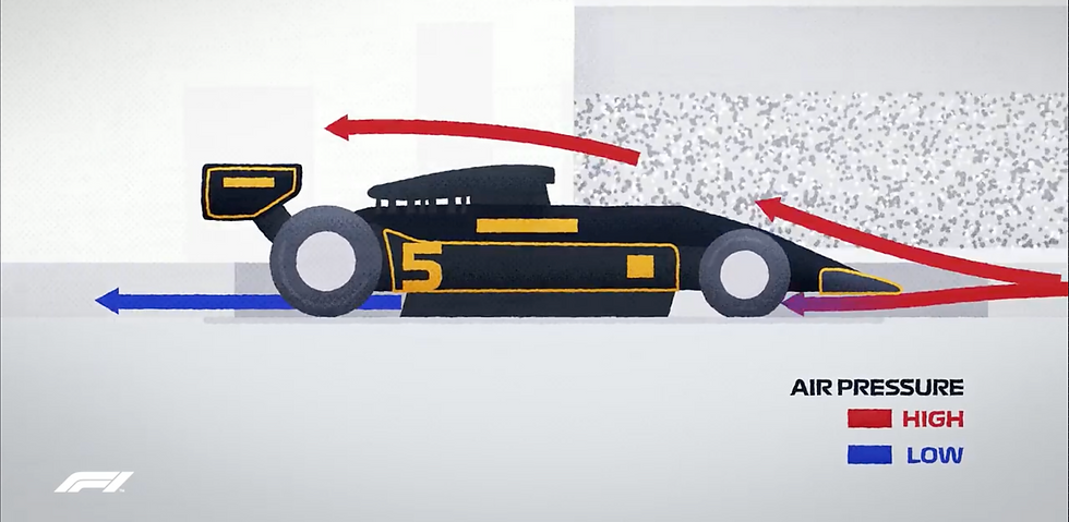
Ground Effect is a series of aerodynamics effects or designs which helps in creating the favourable amount of downforce in a car. allowing for greater grip and this greater cornering speeds.
One of the biggest components in it are wings of an F1 car. Ground effects cars went beyond simple wings – they utilized upside-down aerofoils surrounded by side skirts that went almost all the way down to the road to create zones of extremely low pressure underneath the car. In racing cars, a designer's aim is for increased downforce and grip to achieve higher cornering speeds. A substantial amount of downforce is available by understanding the ground to be part of the aerodynamic system in question, hence the name "ground effect". Designers shifted their efforts at understanding air flow around the perimeter, body skirts, and undersides of the vehicle to increase downforce with less drag than compared to using a wing.
The problem with these extreme ground effects is that if the seal is broken – for example, if the skirts are damaged, the car went over an uneven portion of the road, the car was nudged by another car, et cetera – then a large portion of that downforce would be almost instantly lost, potentially causing the car to hurtle off the track.
The Bernoulli principle is not the only mechanic in generating ground effect downforce. A large part of ground effect performance comes from taking advantage of viscosity. The boundary layer between the two surfaces works to slow down the air between them which lessens the Bernoulli effect. When a car moves over the ground, the boundary layer on the ground becomes helpful. In the reference frame of the car, the ground is moving backwards at some speed. As the ground moves, it pulls on the air above it and causes it to move faster. This enhances the Bernoulli effect and increases downforce.
Barge Boards
Just rearward of the front wing, toward the bottom of the car, are the barge boards. While they provide some downforce in F1 cars, their main job is to focus air around the car so it can be used effectively by the floor and rear wing. Bargeboards are components of F1 cars, and some other open-wheel race cars, which help to redirect air flow and make the car more aerodynamic. They are located between the front wheels and the side pods of the car, and they also help cool internal components through this redirection of air.

It is an aerodynamic component that sits between the front wheel and the side pod, which contains the air intakes for the internal components of the car. The clean air coming across the front of the car is directed into these large air intakes for cooling purposes. The turbulent air that comes off the front tires is redirected away from the body of the car by the vortices created by parts of the front wing as well as some extra parts of the bargeboard itself. These are called turning vanes, and they help to generate vortices that act to create a vortex seal around the base of the car, preventing any turbulent air getting underneath and messing up the balance.
Floor

The floor of the car is just what it sounds like - the bottom of the car. It is actually an aerodynamic element because teams will ensure the body work is as compact as possible towards the center of the car, thus exposing as much of the floor area as possible. This is used to aerodynamic effect to create downforce, particularly just in front of the rear wheels.
Diffuser

One of the key aerodynamic elements from Formula 1 engineering is one you barely even see, called the diffuser. Diffusers utilize the Venturi Effect by shaping bodywork such that air flows from areas of high pressure at the front of the car to low pressure at the rear. That pressure differential effectively sucks the car to the track creating yet more downforce.

The diffuser increases in volume along its length, creating a void that has to be filled by the air passing under the body. This venturi effect means that the flow is accelerated through the throat of the diffuser, creating the desired low pressure, then gradually returned to the same velocity at which it joined the wake (See Figure above). The angle or slope of the diffuser is also important, the diffuser must have a gradual change of angle to prevent flow separation from its roof and sides. The addition of the vertical ‘fences’ to a diffuser help to optimise the diffusers efficiency by ensuring that the air is only drawn only from the underbody and does not spill in from the upper body surfaces.

The figure on the right shows the pressure coefficient of a generic diffuser design, with blue representing lowest pressure areas and red highest pressure. This clearly illustrates the reduction in pressure at the throat area as the velocity increases and the subsequent reduction in pressure for the underfloor as the diffuser sucks the car to the ground.
The velocity of the air decreases as it moves along the diffuser, illustrated in the figures below, which in turn creates the increase in pressure seen above. The figures below illustrate the flow velocity of the air under the body with red showing high velocity and blue showing low.


Rear Wing (RW)
Purpose
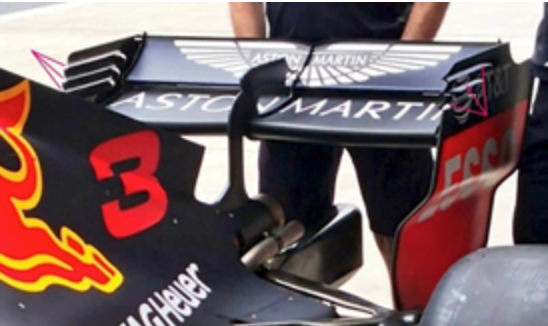
The RW counterbalances downforce generated from the Front Wing. It does not exploit ground-effects, and generates ~10% less downforce than the Front Wing. It can be tuned to adjust downforce distribution across the front and rear wheels. More downforce correlates to greater grip on the rear tires, favoured especially while turning, and lower drag correlates to higher acceleration and maximum speeds, favoured on straights.
Components of RW

1. Main-plane

The main-plate acts as an upside-down aerofoil, and is the main component in downforce generation. While briefly mentioned in the earlier sections (Bernoulli’s Equation & Concept of Downforce), I will give an in-depth explanation.

Figure: Airflow represented by arrows, colour indicating the airflow speed
There are 2 air streams, one flowing past the upper surface (0U→1U→2U→3U), and the other flowing past the lower surface (0L→1L→2L→3L).
At 0U→1U, the leading edge of the aerofoil blocks the upper stream from going forwards, deflecting it upwards along the top surface. This slows down the airflow, by Bernoulli’s Equation, increasing air pressure. At 1U→2U→3U, the upper stream slowly accelerates along the upper surface, before finally leaving the aerofoil at an inclined angle.

Whereas, at 0L→1L, the lower stream must navigate the sharp curvature of the aerofoil, narrowing its path. As the airflow rate is constant before and after 1L, air at 1L must dramatically increase in velocity. By Bernoulli’s Equation, the air pressure will be very low. At 1L→2L→3L, the upper stream slows down along the upper surface, before finally leaving the aerofoil at an inclined angle.
Since there is a pressure difference vertically, air above and below will push the aerofoil downwards, producing downforce. Additionally, since air is pushed upwards by the RW, by N3L, the air exerts downforce onto the RW.

Figure: Symmetric aerofoil with wake, aerofoil with flaps without wake
The reason for the asymmetry in a RW is due to pressure drag. To increase downforce generated, we increase the angle of attack (AOA). This will further increase the pressure difference vertically, and direct air further upwards, which by N3L, means even more downforce generated. However, increasing AOA makes the aerofoil blunter (Cross-sectional area increases), and past a certain angle, the lower stream will separate from the aerofoil, causing a wake, or chaotic flow. As mentioned in a previous section (Pressure Drag), this undesirably increases pressure drag.

Figure: Symmetric vs Asymmetric aerofoil
Whereas, the RW’s asymmetric aerofoil has a curve from the front to the rear. The curvature the lower airstream navigates around is much less steep (1L), better sticking to the surface, increasing the angle before flow separation occurs. The figures above show the asymmetric aerofoil has significantly lower pressure at 1L & 2L. Even with a slightly higher pressure on the upper surface on the asymmetric aerofoil, the asymmetric aerofoil has a significantly higher pressure difference vertically, contributing much more downforce. If we need even more downforce, we can further increase the AOA, albeit increasing drag as well.
2. Flap

The flap acts as an extended upside-down aerofoil to the main plate, further increasing downforce, increasing the car’s grip through turns. On certain long straights, it is opened by DRS system, decreasing drag, increasing acceleration and maximum speed. (Albeit lower downforce, so it cannot be used while turning). As such, having a dynamic flap and a main-plate compared to a longer main-plate is favourable, as it does not contribute to more drag on DRS-straights.
3. Endplates


Figure: Cambered wing with wingtip vortices
For a 3D aerofoil, towards the wingtips, the low pressure on the lower surface sucks the upper air-flow downwards, reducing the downforce generated. Additionally, as the air leaks from the top to the bottom, air flow around the wing pushes this leaking air downstream, resulting in strong vortices behind the aerofoil, on both sides, dramatically increasing drag.
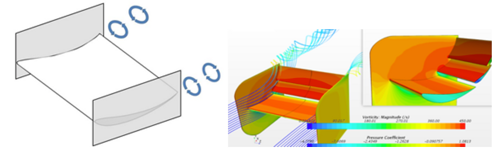
Figure: Cambered wing with endplates and smaller wingtip vortices
The solution F1 RWs use is to add endplates on both ends, blocking any flow leakage from the top to bottom surface. This significantly reduces wing tip vortices, minimizing drag.


Comments